Author

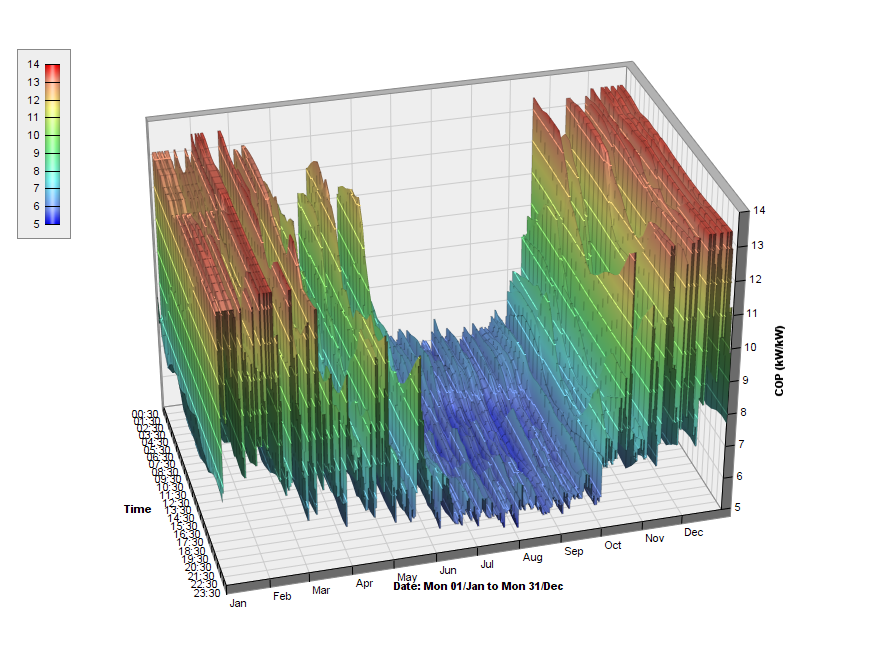
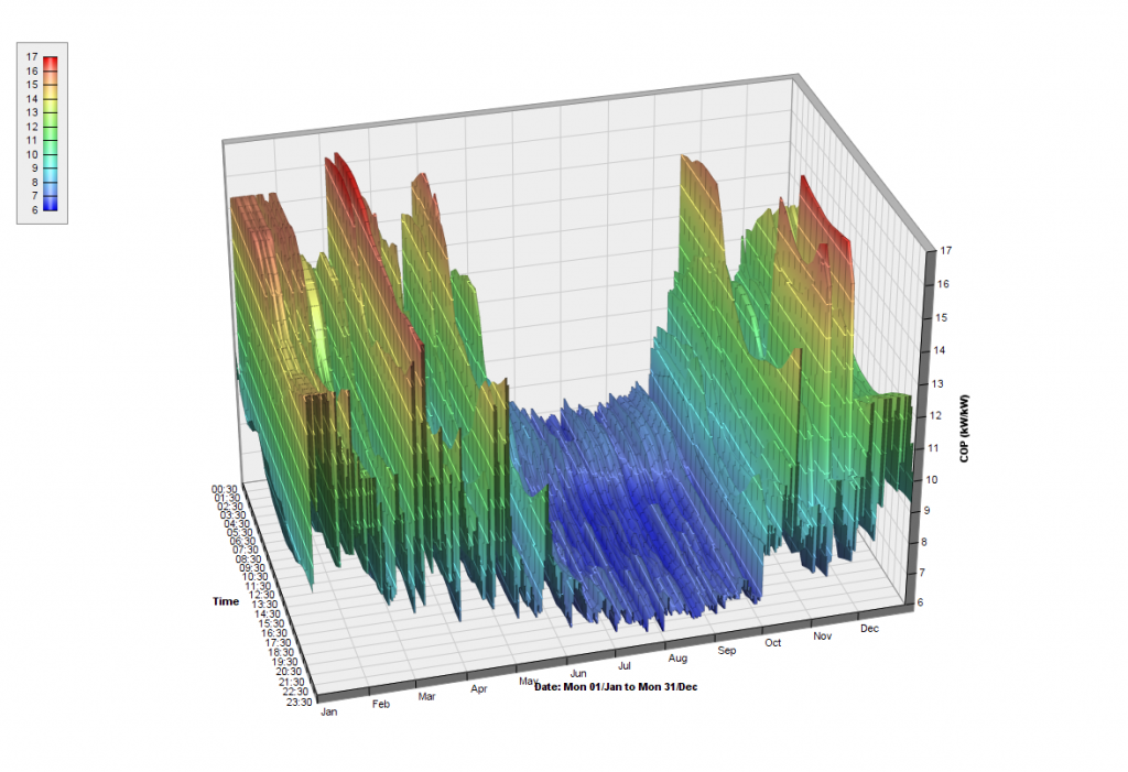
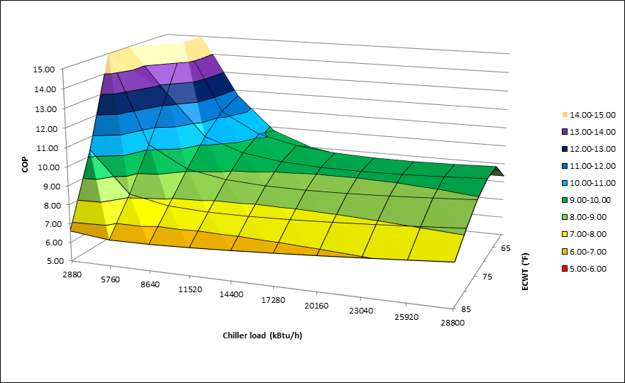
Water-cooled chiller plants are traditionally designed with the evaporators and condensers piped in parallel, which makes the compressor in each machine have to do the entire cooling delta T and lift. Lift is the difference between leaving evaporator pressure and leaving condenser pressure. This is often approximated by the leaving temperatures.
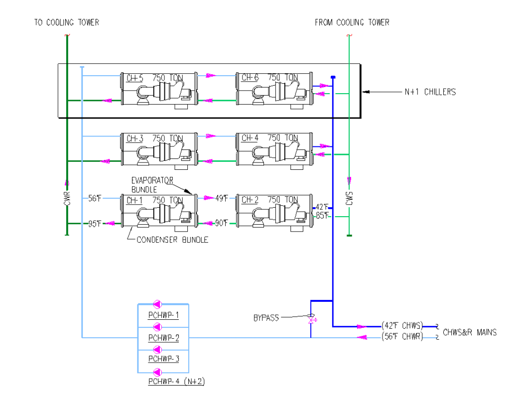
Configuring water-cooled chiller plants in a series counterflow (SCF) arrangement splits the lift between two machines to enhance the operating efficiency of the plant. In a SCF configuration the chiller making the coldest chilled water also gets the coldest condenser water. Now one machine will cool the water from 56 F° to 49 F° and the second machine cools it from 49 F° to 42 F°. Just like in life, splitting the work results in a more efficient outcome. Our analysis has shown SCF configurations saving 15-20% compared to typical parallel configurations with full load efficiencies below 0.5 kW/ton (COP=7).