
Author

Looking For Savings in Unlikely Places
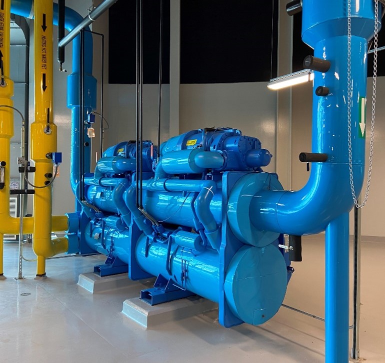
The second article in this TPA Central Utility Plant (CUP) chilling series is about…well, producing chilled and hot water at the same time. This is accomplished through the use of Heat Recovery Chillers (HRCs), which reject condenser heat to the hot water loop instead of to a cooling tower (as in a conventional water-cooled system). This reduction in conventional boiler load is an excellent opportunity to save energy when simultaneous heating and cooling are required.
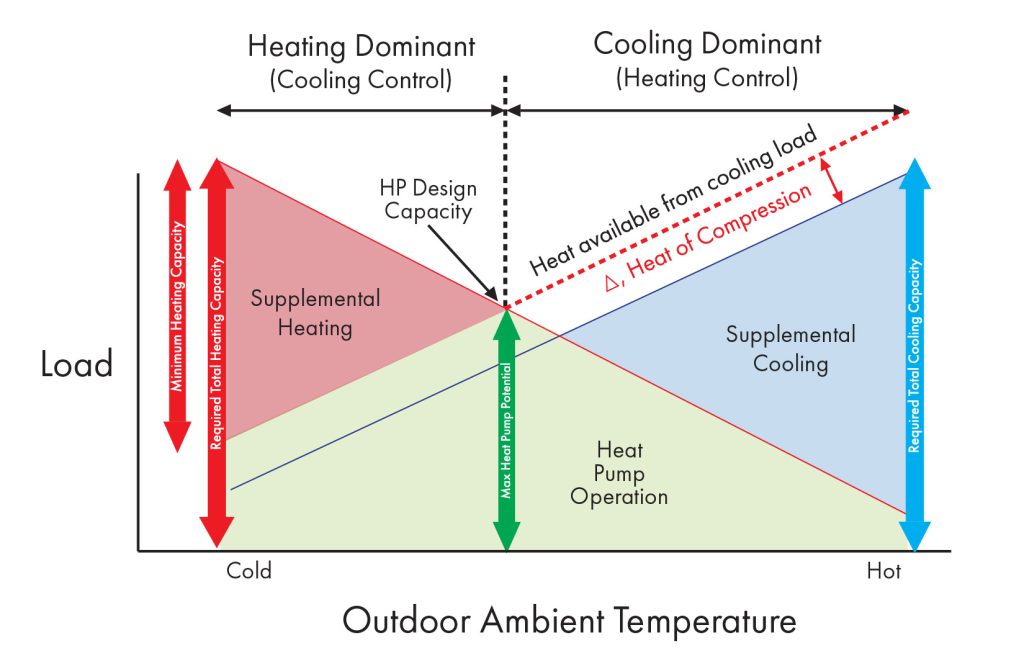
For this facility, a sixth of the peak cooling load is equivalent to the peak heating load. Therefore, it doesn’t take much cooling capacity to create the heat needed to serve the Main Terminal in the winter, and even less for reheat mode during dehumidification.
When designing the Heat Recovery Chiller, the first step is to find the point at which the simultaneous demand for heating and cooling is maximized, as shown in Figure 1. This point is not likely to be equal to either the peak heating or cooling load. The chilled water loop must be balanced so that the amount of cooling being put back into the loop is equal to the amount being used. This means that cooler chilled water needs to be added to the loop ahead of the primary chiller return inlets in the case of the CUP.
Heat Balance Cross-Plot
This approach was chosen because the chilled water system volume (roughly 25,000 gallons) has significant thermal inertia and the risk of cycling the HRC from overcooling the loop too quickly could be minimized. Even during the coldest part of the winter, the airport has a year-round demand for cooling to support telecommunication and data rooms, food refrigeration equipment, baggage handling, screening areas, and similar spaces.
Trend Data (January and February 2022)
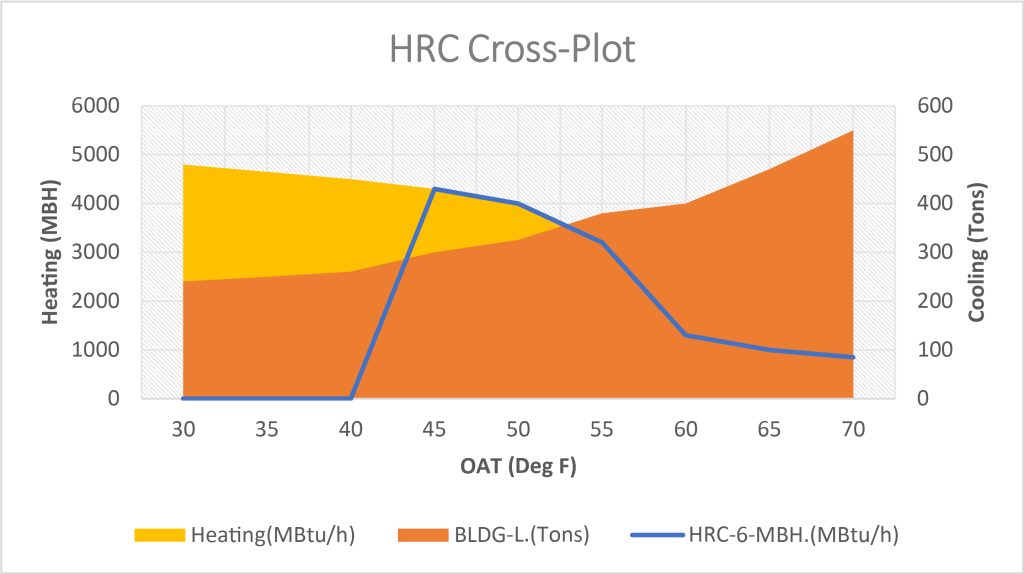
As mentioned earlier, the HRC was put ahead of the primary chillers in a pre-cool position. The original design intent was that the resulting 50-55°F chilled water temperature would be adequate for internal cooling in the winter. However, the owner’s preference was to limit the CHW reset from 42°F to a max of 48°F due to concerns with internal space temperatures drifting out of range, causing the main chillers to run. In doing so, the equipment would need at least 25% load, 35% realistically, to keep out of hot gas reheat. The bottom-end HRC operation is a minimum building load of 300 tons to keep the lead chiller online. In Figure 2, the plot shows the HRC (blue line) is off until 40°F outside and can remain on while providing primary building heating up to 60°F, then reheat for dehumidification. The figure shows a 2-month trend to illustrate the real-life operation.

It’s not a complete loss since the condensing boilers are running on the coldest days and may have condensing flue gasses. Cold return water temperatures are needed to do that, which may not be seen in the shoulder months when outdoor temperatures are mild. Hurrah!
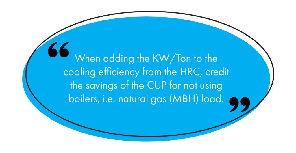
Not running all of the cooling towers is not necessarily an obvious place to recover savings but worth considering. Because the on-premise water source heat pump moves energy from a source to a load within a closed loop, the heat rejection that the main chillers would burden the cooling towers with, efficiency is increased. The moral to this chilling story is that for every ton offset with an HRC, water, water treatment, fan, and pump energy can be saved.
Learn About TLC’s Aviation Team of Experts and Explore TLC’s Aviation Portfolio, HERE